
Temporary Roofing System User Guide
What temporary roofing is
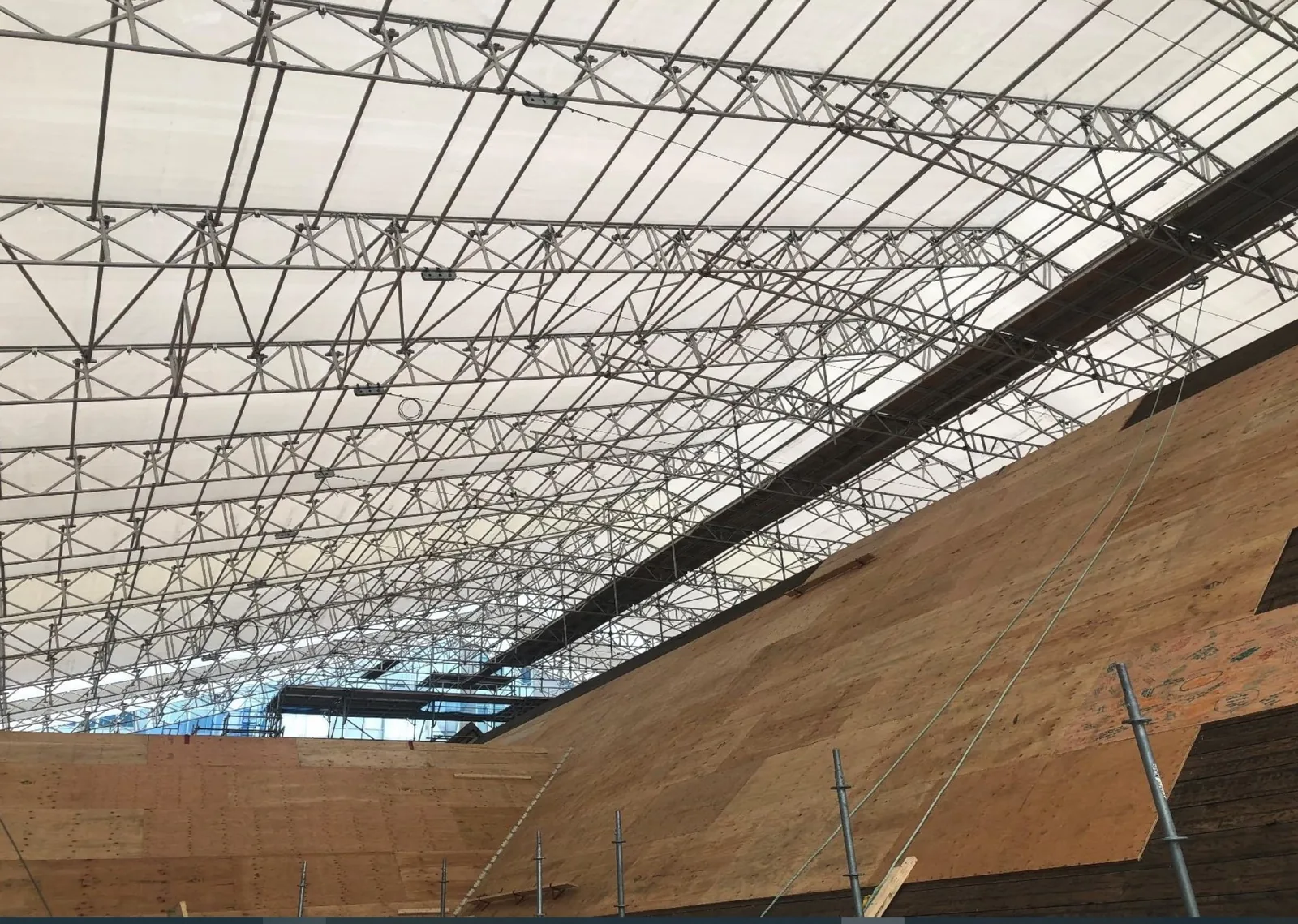
Temporary roofing is a sheeted structure designed to protect the area inside from weather, dust, containment and other site hazards. This guide is intended to give suppliers and erectors the information they need to build temporary roofs for use by contractors during the construction process.
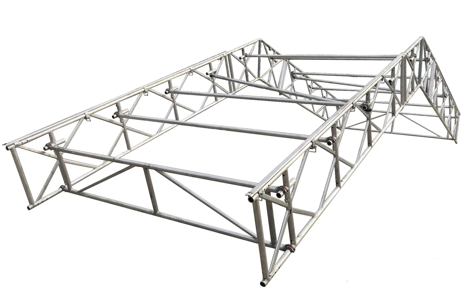
The system described here is an all-aluminium modular temporary roofing assembly composed of 780 diamond beams, K-frames, horizontal braces and roller braces, covered by either shrink-wrap or keder sheets. A key advantage of the diamond-beam roofing system is the option of using cross-braces instead of K-frames, or a combination of both, to suit the site and loading conditions.
The temporary roof can be supported by the existing building, by scaffolding or by any other suitable support. However, the supporting structure must always be checked and designed by a competent engineer to ensure it can withstand the loads that the roof generates.
Temporary roofing can be installed by three main methods, depending on site conditions:
- Hand-built installation — built bay-by-bay in the air.
- Roll-out installation — prefabricated modules are rolled along runway beams.
- Crane-assisted installation — complete bays are assembled on the ground and lifted into position.
Standard roof forms
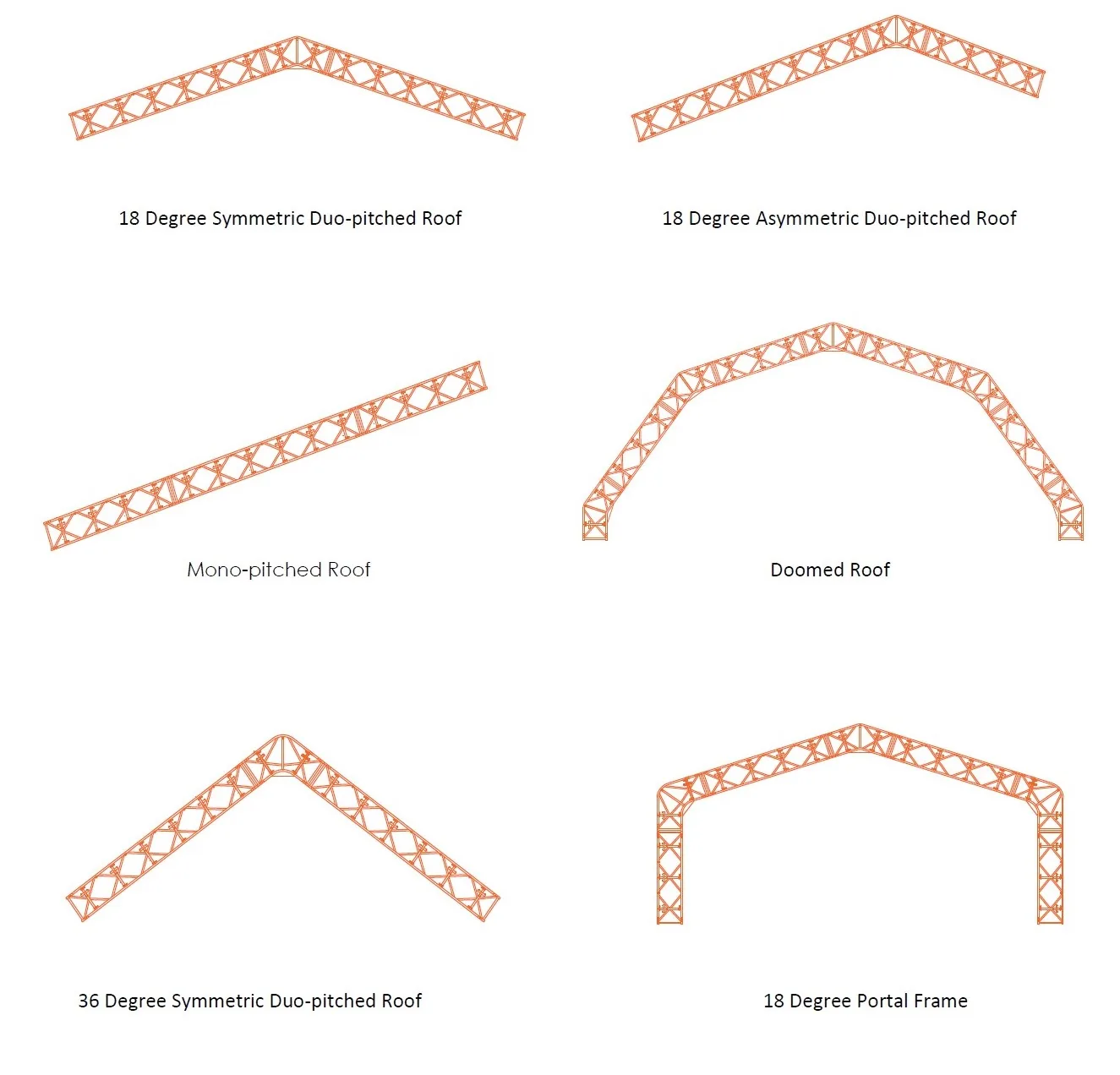
The modular aluminium beams are available in various lengths to accommodate the required span. Beams are joined together using steel spigot connections. The six common configurations are:
- 18° symmetric duo-pitched roof
- 18° asymmetric duo-pitched roof
- Mono-pitched roof
- Domed roof
- 36° symmetric duo-pitched roof
- 18° portal frame
Select the form that matches the building geometry, drainage requirements and the slope needed for snow or water shedding.
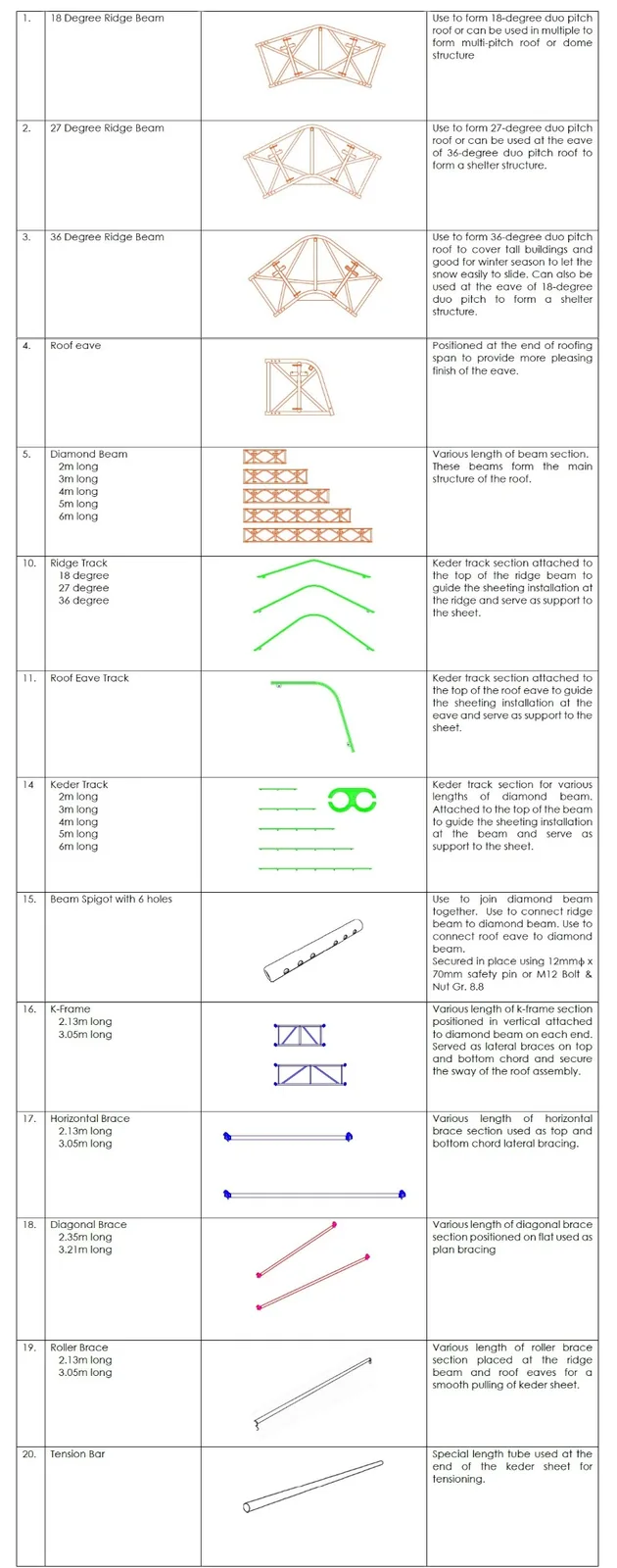
Key components
Primary structural components
| Component | Typical sizes / details | Function |
|---|---|---|
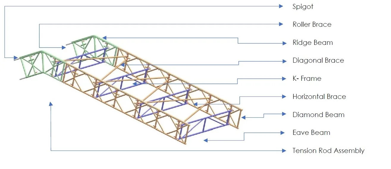
| 18° ridge beam | Angled top chord | Forms 18° duo-pitch roofs; can be combined for multi-pitch or domed structures. |
| 27° ridge beam | Angled top chord | Forms 27° duo-pitch roofs; can be used at the eave of a 36° roof to form a shelter. |
| 36° ridge beam | Angled top chord | Forms 36° duo-pitch roofs for tall buildings and good snow shedding. |
| Roof eave | End-of-span section | Positioned at the end of the roofing span to provide a clean eave finish. |
| Diamond beam | 3 m, 4 m, 5 m, 6 m | Forms the main structure of the roof. |
| K-frame | 2.13 m, 3.05 m | Vertical lateral brace attached to diamond beams; prevents sway of the assembly. |
| Horizontal brace | 2.13 m, 3.05 m | Top and bottom chord lateral bracing. |
| Diagonal brace | 2.13 m, 3.05 m | Plan bracing positioned on the flat. |
| Roller brace | 2.13 m, 3.05 m | Placed at ridge and eaves for smooth pulling of the keder sheet. |
| Tension bar | Special length | Used at the end of the keder sheet for tensioning. |
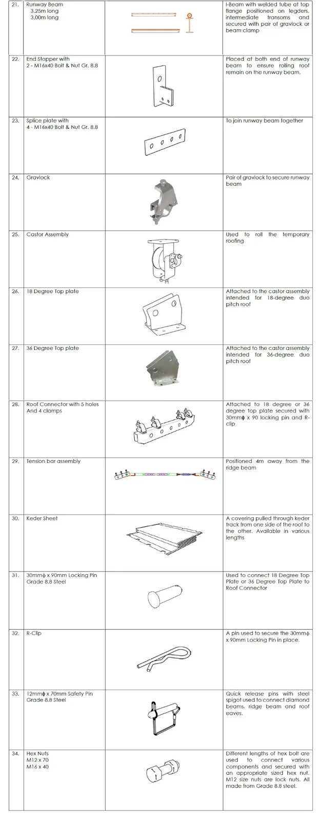
Tracks, sheeting and fixings
| Component | Typical sizes / details | Function |
|---|---|---|
| Ridge track | 18°, 27°, 36° | Guides and supports the keder sheet at the ridge. |
| Roof eave track | Matching eave profile | Guides and supports the keder sheet at the eave. |
| Keder track | 2 m, 3 m, 4 m, 5 m, 6 m | Attached to the top of diamond beams to guide and support the sheeting. |
| Beam spigot with 6 holes | 12 mm × 70 mm pin or M12 bolt & nut Gr. 8.8 | Joins diamond beams; connects ridge beam and roof eave to diamond beams. |
| Runway beam | 3.25 m, 3.00 m | H-beam with welded tube; carries rolling roof modules. |
| End stopper | 2 × M16 × 40 bolt & nut Gr. 8.8 | Prevents rolling roof from leaving the runway beam. |
| Splice plate | 4 × M16 × 40 bolt & nut Gr. 8.8 | Joins runway beams end-to-end. |
| Gravlock | Pair | Secures runway beam to the support. |
| Castor assembly | Swivel / fixed | Allows the temporary roofing to roll. |
| 18° / 36° top plate | Attached to castor assembly | Supports the roof connector at the correct pitch. |
| Roof connector | 5 holes, 4 clamps, 30 mm × 90 mm locking pin + R-clip | Connects top plate to the truss. |
| Tension bar assembly | Positioned 4 m from ridge | Tensions the keder sheet. |
| Keder sheet | Various lengths | Covering pulled through the keder track from one side to the other. |
| 12 mm × 70 mm safety pin | Grade 8.8 steel | Quick-release pins for connecting diamond beams, ridge beams and roof eaves. |
| 30 mm × 90 mm locking pin | Grade 8.8 steel | Connects top plates to roof connectors. |
| R-clip | Spring steel | Secures locking pins. |
| Hex nuts / bolts | M12 × 70, M16 × 40 | Grade 8.8 steel fixings for components and runway. |
Hand-built installation
The connection between the roofing and any support structure must follow the design produced by a scaffold engineer. The general hand-built sequence is:
- Build a temporary scaffold tower at mid-span of the roof as a working area, starting from one gable end to the other.
- Assemble the ridge beam (track included) at the exact height and connect it to diamond beams (track included) using the spigot with six safety pins to complete the first truss. Temporarily support the truss with short vertical tubes and right-angle clamps.
- Install the eave beam (track included) at the ends of the roof truss.
- Secure the first truss to the existing perimeter scaffold support as per the engineer's design.
- Repeat steps 2–4 to assemble the next truss on the next bay location.
- Attach the correct size of K-frame at the eaves and fix the next K-frame upslope to the ridge beam at 2 m intervals.
- Install horizontal braces between the K-frames at the top chord to create 1 m lateral bracing for the compression chord.
- Install the roller braces located at the ridge beam and roof eaves, inserted into the pockets provided.
- Install diagonal braces at 1 m intervals in a zig-zag arrangement from ridge down to eaves.
- At this stage the first braced bay roof is completed.
- Repeat steps 2–4 to assemble infill bays. Install four infill bays, then repeat the braced bay installation.
- Once the truss is assembled, install the correct size of horizontal braces at the eaves and fix the next horizontal brace upslope to the ridge beam, spaced at 1 m intervals for the top chord and 2 m intervals for the bottom chord.
- Install the roller braces located at the ridge beam and roof eaves.
- Repeat steps 10–12 to complete the four infill bays.
- Once the four infill bays are completed, repeat the steps to install the braced bay.
- Continue installing infill bays and braced bays until the required roof length is completed.
- Once the roof structure is completed, pull the keder sheet over the track and secure it to the scaffold. The sheet can be installed sequentially, one bay at a time.
- Once the roof is completely covered, dismantle the temporary scaffold tower.
Roll-out installation
Roll-out installation is useful where a stepped working platform can be established at one gable end and the roof can be progressively rolled into position.
- Create a stepped working-platform scaffold at one gable end of the roof. Once this platform is established, operatives can build the first braced bay.
- Place runway beams on top of the ledgers/transoms at a maximum spacing of 1.2 m, secured with pairs of beam clamps. Attach the end closer with two M16 × 40 bolts at one end only. Connect runway beams with pairs of joint plates and four M16 × 40 bolts to complete the full roof length. Attach the end closer with two M16 × 40 bolts at the other end.
- Create a rolling roof assembly by connecting the castor assembly to the 18° top plate using four M12 × 40 bolts, and attach the roof connector using two Ø30 mm × 90 mm locking pins.
- Using the stepped working platform, assemble the first truss to the desired width using the ridge beam and diamond beams connected by six Ø12 mm × 70 mm safety pins. Temporarily support the truss with short vertical tubes and right-angle clamps. Secure the assembled first truss to the roof connector on both sides, making sure the rolling roof assembly is vertical.
- Slide another rolling roof assembly on each runway beam to the desired bay-width distance from the first truss. Complete a new truss section, temporarily support as before and connect it to the new pair of rolling roof assemblies.
- Attach the correct size of K-frame at the eaves and fix the next K-frame upslope to the ridge beam at 2 m intervals.
- Install horizontal braces between the K-frames at the top chord to create 1 m lateral bracing for the compression chord.
- Install the roller braces located at the ridge beam and roof eaves, inserted into the pockets provided.
- Install diagonal braces at 1 m intervals in a zig-zag arrangement from ridge down to eaves.
- At this stage the first braced bay of the rolling roof is completed. Disconnect the trusses from their temporary tube support and roll them out.
- Repeat step 5 to assemble infill bays in the positions vacated by the first braced bay. Install four infill bays, then repeat the braced bay installation.
- Once the truss is assembled, install the correct size of horizontal braces at the eaves and fix the next horizontal brace upslope to the ridge beam at 1 m intervals for the top chord and 2 m intervals for the bottom chord.
- Install the roller braces located at the ridge beam and roof eaves.
- Repeat steps 10–12 to complete the four infill bays.
- Once the four infill bays are completed, repeat the steps to install the braced bay.
- Continue installing infill bays and braced bays until the required roof length is completed.
- Once the roof structure is completed, install additional tube and fittings at the support locations in accordance with the scaffold engineer's design.
- Pull the keder sheet over the track and secure it to the scaffold. The sheet can be installed sequentially, one bay at a time.
Crane-assisted installation
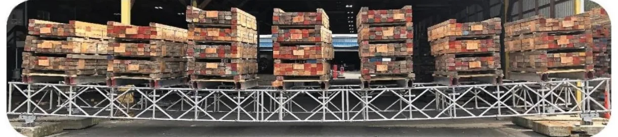
Crane-assisted installation is the fastest method for large roofs. The basic sequence is:
- Ensure that the perimeter scaffold support is ready to receive the crane-lifted roof in accordance with the scaffold engineer's design.
- Establish a space where roof bays can be assembled on the ground. Segregate the space to protect the public.
- At ground level, create a temporary stepped working-platform scaffold to be used for assembling the craneable roof.
- Establish the correct height of the ridge beam. Connect two ridge beams (track included) with the desired length of brace frames, supported by horizontal tube and fittings. Secure the roller braces into the pockets provided.
- Attach diamond beams to the ridge beams using steel spigots with six Ø12 mm × 70 mm locking pins.
- Connect the diamond beams for the desired length and attach the roof eave at both sides. All joints use steel spigots with six Ø12 mm × 70 mm locking pins.
- Continue installing K-frames from the ridge down to the eaves at 2 m intervals.
- Install horizontal braces between the K-frames at the top chord to create 1 m lateral bracing for the compression chord.
- Install the roller braces located at the roof eaves.
- Install diagonal braces at 1 m intervals in a zig-zag arrangement from ridge down to eaves.
- At this stage the first braced bay roof is completed and ready for craning.
- Attach the sling to the lifting points determined by the scaffold engineer. Four lifting points are required, with the sling positioned at an angle not less than 70° from horizontal.
- Lift the first fully braced bay into position and connect it to the scaffold, ensuring the bay is correctly aligned. Secure the truss to the scaffold in accordance with the engineer's design. Hand lines may be tied to the beams at the eaves before lifting to help guide the bay when lowering it into position.
- Create a second fully braced bay at ground level by repeating steps 4–12.
- Lift the second fully braced bay into position. A horizontal brace can be used at the eaves to establish the correct distance from the first bay. Secure the truss to the scaffold in accordance with the engineer's design.
- The infill bay between the braced bays can now be completed. Working progressively from the ridge down to the eaves, install horizontal braces spaced at 1 m intervals for the top chord and 2 m intervals for the bottom chord.
- Install the roller braces at the ridge beam and roof eaves, inserted into the pockets provided.
- Continue the process until all bays are complete and fixed to the supporting structure in accordance with the engineer's design.
- Pull the keder sheet over the track and secure it to the scaffold. The sheet can be installed sequentially, one bay at a time.
Keder sheet installation
Prevailing weather conditions determine whether it is safe to commence sheeting, because the sheets are vulnerable to high winds.
- Sheeting is ideally carried out by four operatives, two on each side of the roof.
- Two ropes must be deployed over the roof from one side to the other before sheeting starts.
- Ensure sheets are leaf-folded, clean and fit for use. Visually check the keder bead for cuts or damage. Do not use damaged sheets.
- Place the sheeting on the working platform directly below the bay to be sheeted.
- Insert the tension tube through the pockets at the edge of the sheet and attach the previously deployed ropes securely to the tension tube at the two outer cutaways.
- Insert rollers into the tracking on each side.
- Insert the keder beads into the tracking up to 1.5 m in depth to ensure correct alignment. Gradually and evenly pull the ropes to slide the sheeting across the roof within the tracking.
- When the sheet is fully pulled over, fit another sheet tension tube into the other edge pockets. Secure the tension tubes at each side with four ratchet straps to the existing scaffold ledgers or tubes.
- Sheets can be installed sequentially as each bay is completed, or all together once the full roof is assembled.
Bracing arrangements
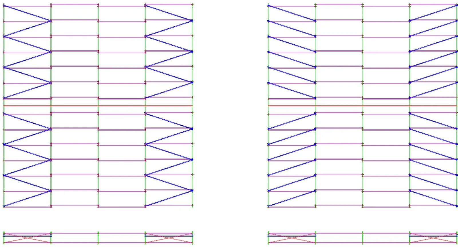
The bracing layout depends on whether the roof is built manually or crane-assisted, and whether K-frames or cross-braces are used. The three standard arrangements are summarised below.
Manual build using cross-braces
| Item | Requirement |
|---|---|
| Braced bays | 1 in 3, plus 1 at each gable end |
| Cross-brace spacing | 1 m in vertical position |
| Handrail spacing | 1 m on top chord, 1 m on bottom chord |
| Diagonal brace spacing | 1 m in zig-zag or single-angle arrangement |
| Infill bays | Maximum 2 unbraced bays before next braced bay |
| Horizontal brace spacing | 1 m on top chord, 2 m on bottom chord |
Crane assist using K-frames
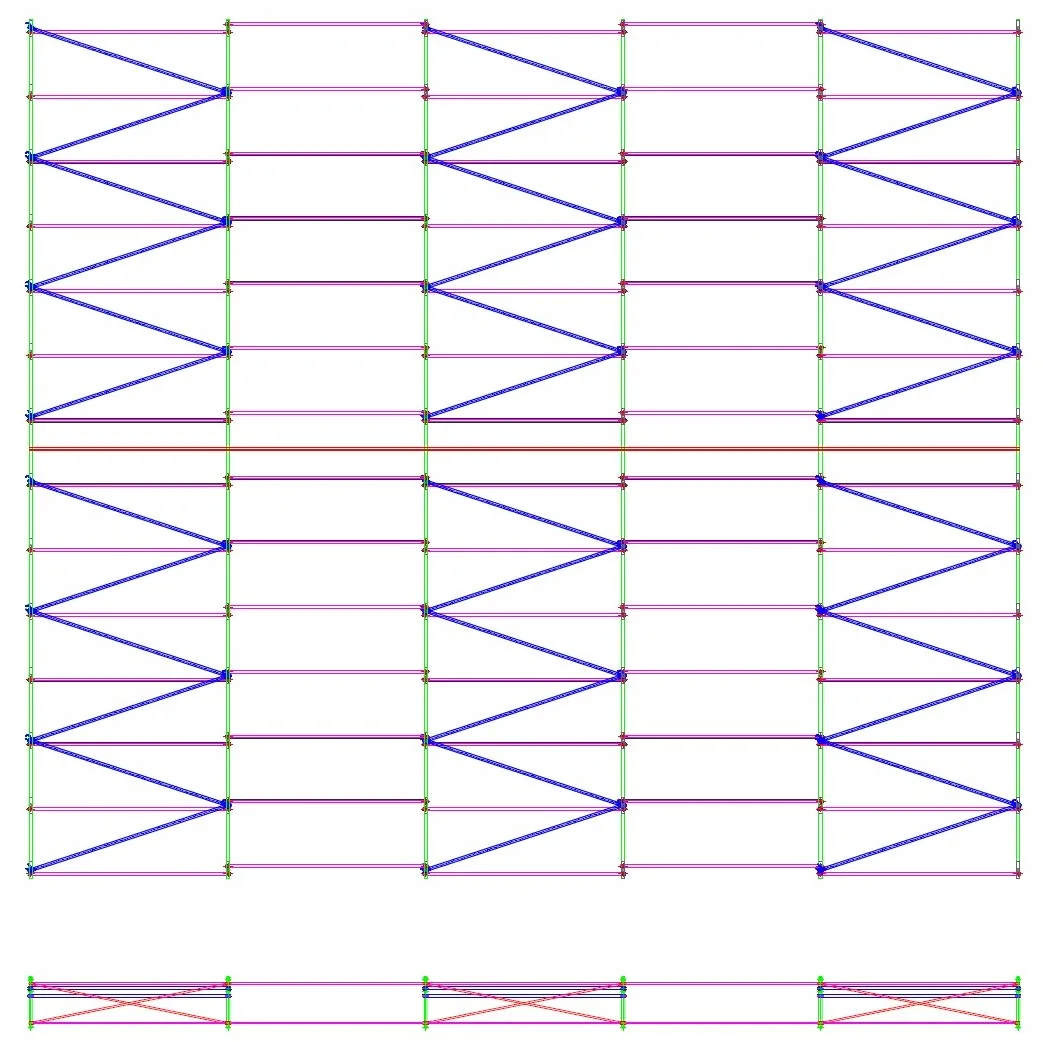
| Item | Requirement |
|---|---|
| Braced bays | 1 in 2, plus 1 at each gable end |
| K-frame spacing | 2 m in vertical position |
| Horizontal brace spacing | 2 m between K-frames |
| Diagonal brace spacing | 1 m in zig-zag arrangement |
| Infill bays | Maximum 1 unbraced bay before next braced bay |
| Horizontal brace spacing (infill) | 1 m on top chord, 2 m on bottom chord |
Crane assist using cross-braces
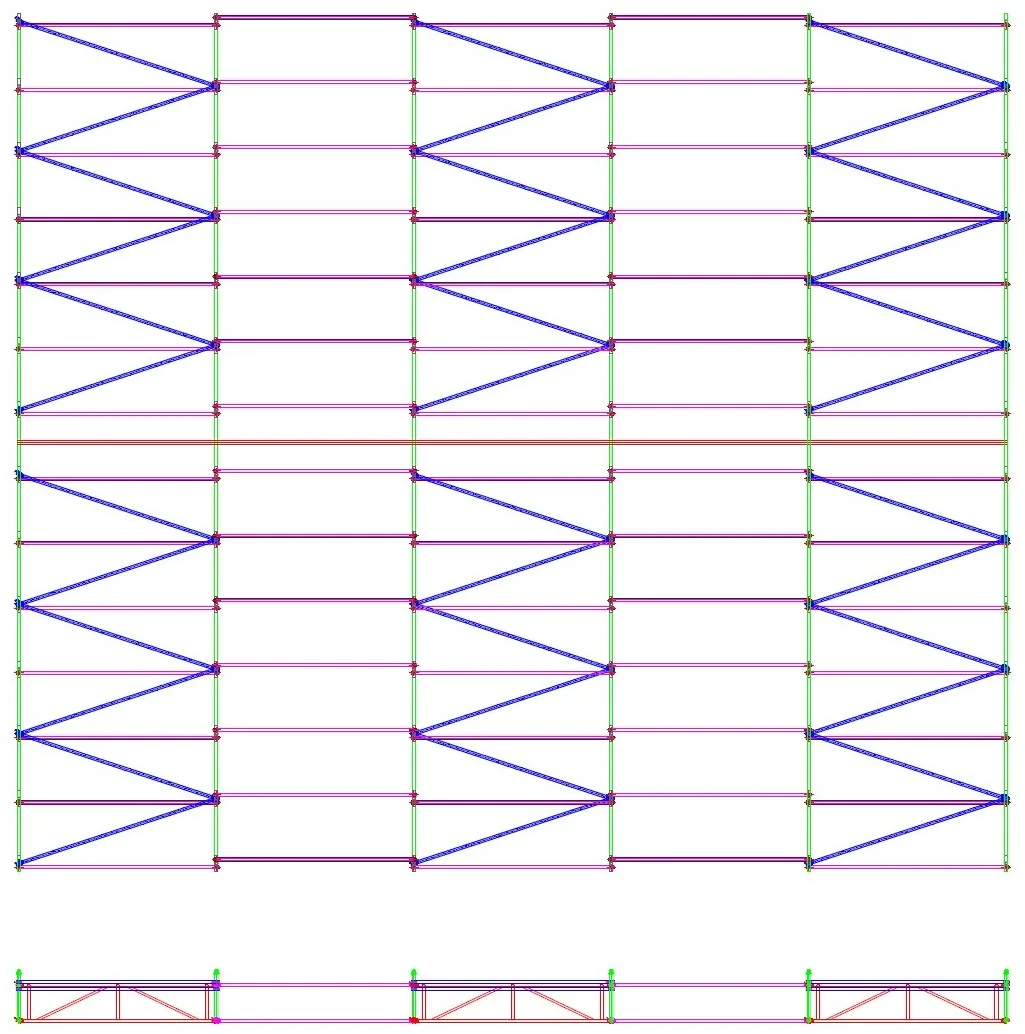
| Item | Requirement |
|---|---|
| Braced bays | 1 in 2, plus 1 at each gable end |
| Cross-brace spacing | 1 m in vertical position |
| Handrail spacing | 1 m on top chord, 1 m on bottom chord |
| Diagonal brace spacing | 1 m in zig-zag or single-angle arrangement |
| Infill bays | Maximum 1 unbraced bay before next braced bay |
| Horizontal brace spacing | 1 m on top chord, 2 m on bottom chord |
Project progress photos
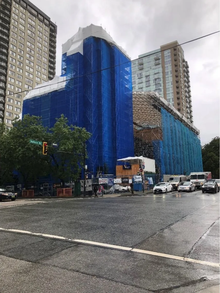
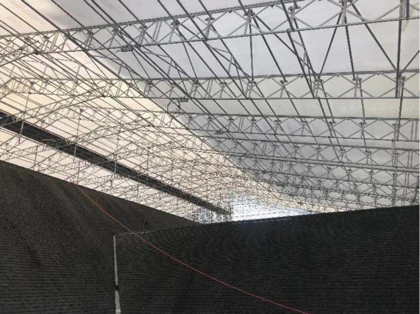
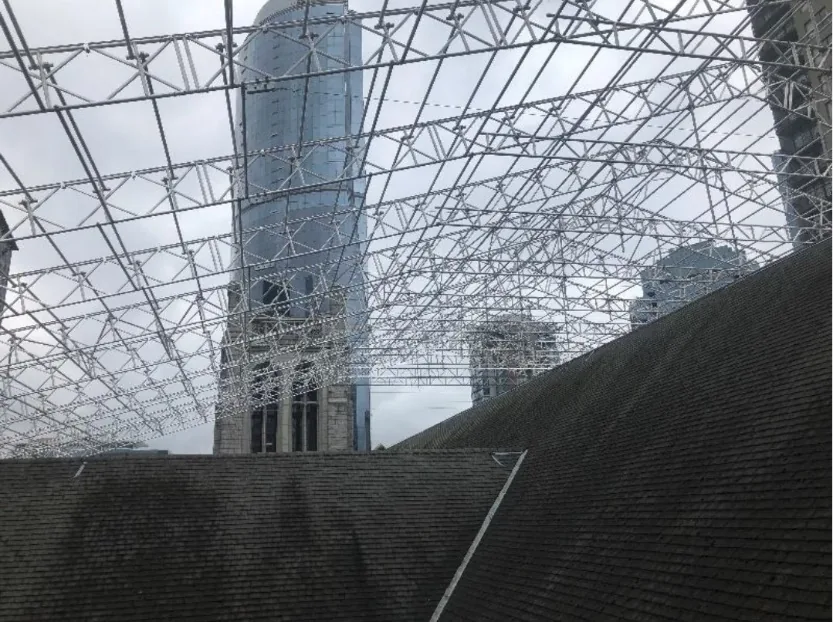
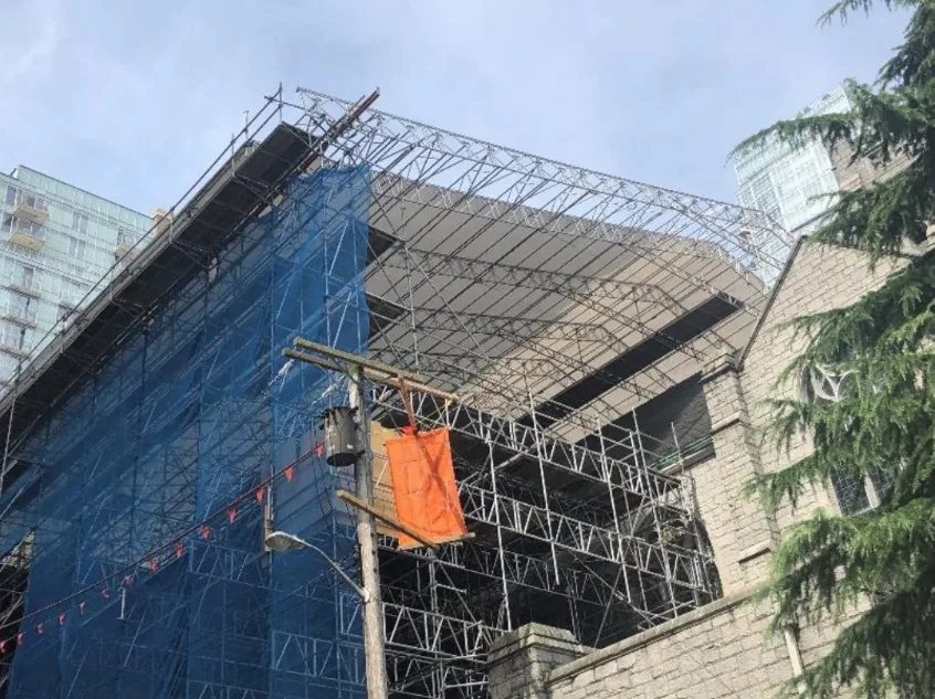
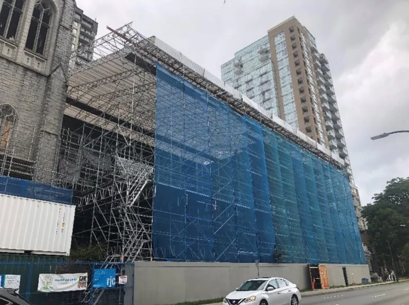
The following photographs show real ACE SCAFFOLD temporary roofing installations on site.
Conclusion
Whether you build the roof by hand, roll it out or crane it in, the same principles apply: follow the engineer's design, use the correct components, brace every bay and fix the sheeting securely. For system dimensions, load capacities and project-specific design support, view the Temporary Roofing System product page or contact the ACE SCAFFOLD team.
More from ACE SCAFFOLD News
- What is ICF means
- ICF bracing setup
- Bracing for ICF House
- Advantages of ICF House
- Ringlock Scaffolding: The Modular System Built for Speed
- Why Contractors Choose Cuplock Scaffolding for Heavy Loads
- Frame Scaffolding: The Reliable Workhorse of the Job Site
- Steel Props: Adjustable Shoring Made Simple
- Scaffold Planks: Steel vs Aluminum Walk Boards
- Aluminum Mobile Scaffold Towers for Fast Indoor Access
- 14 Common Scaffolding Safety Hazards and How to Prevent Them